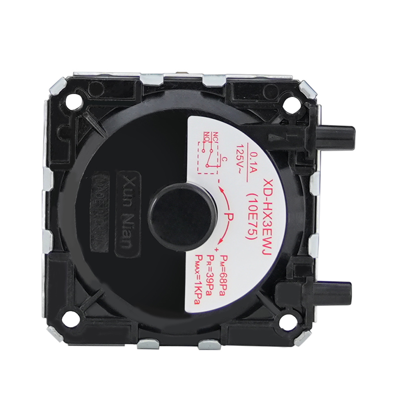
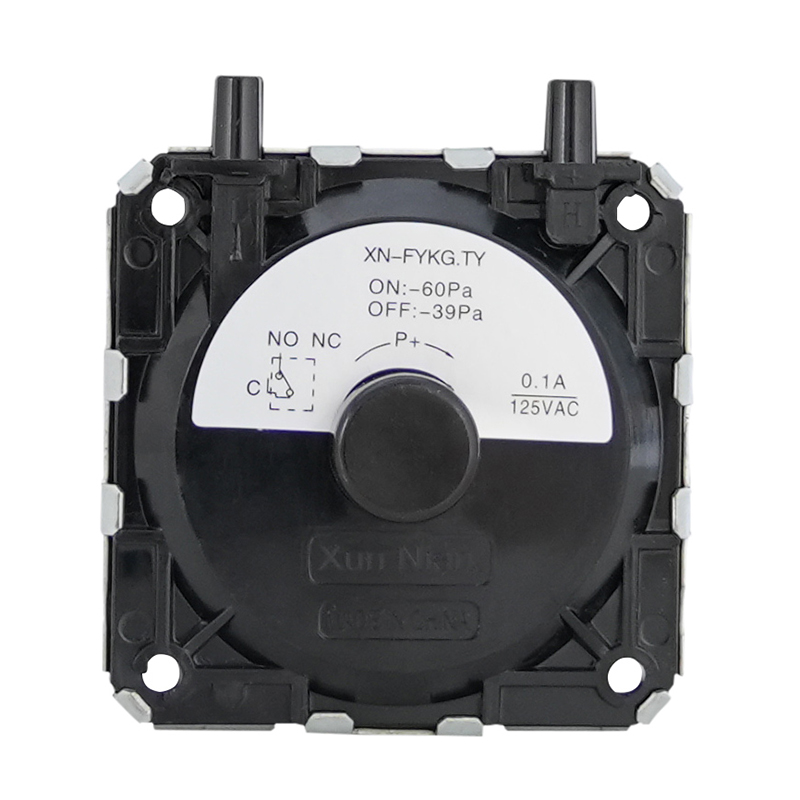
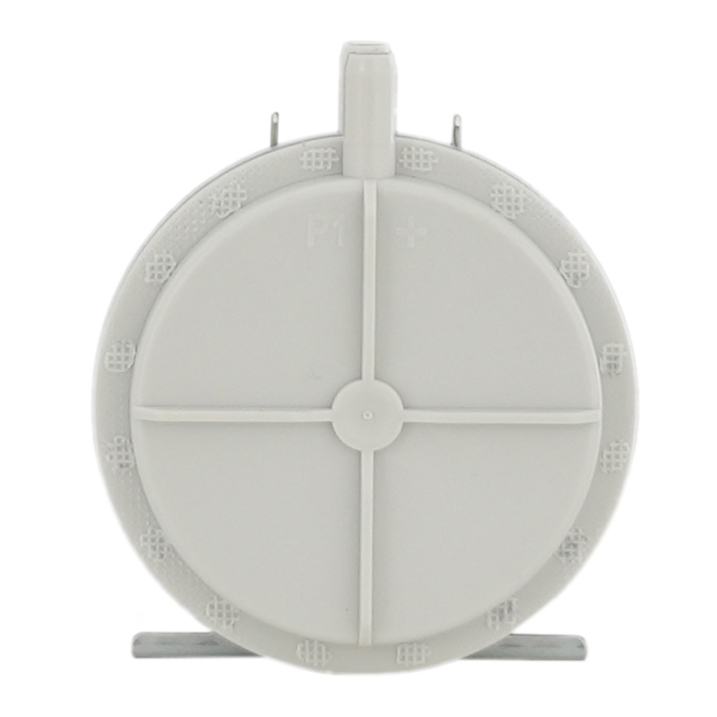
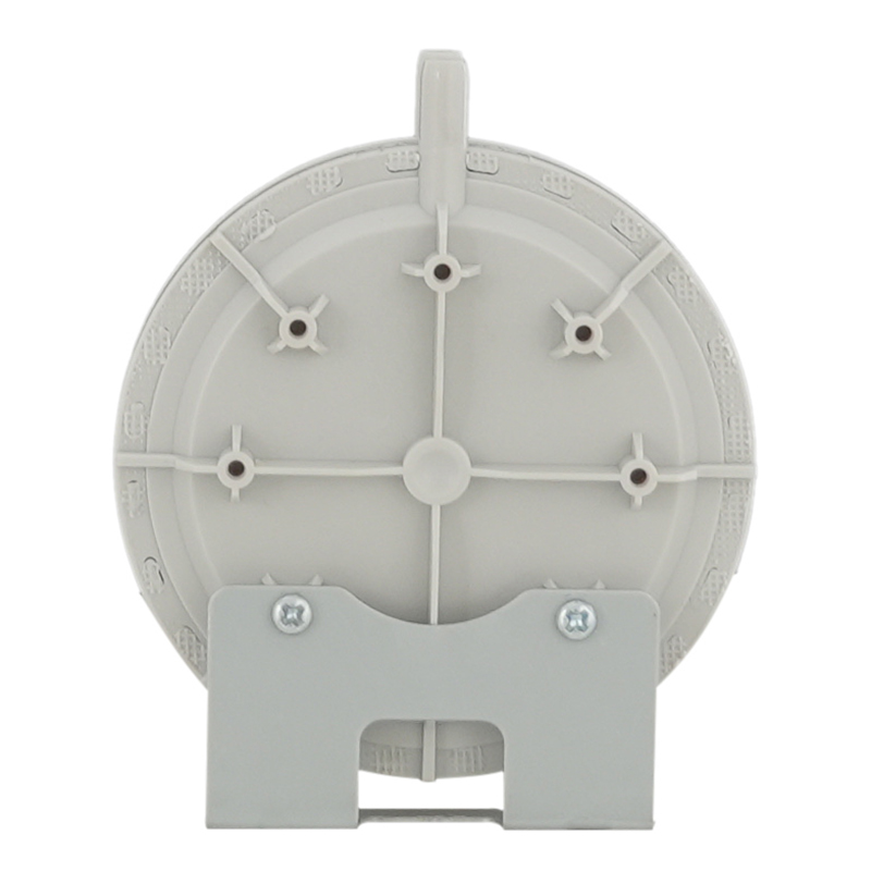
Pressure switches play a crucial role in systems such as HVAC, compressors, water pumps, and boilers. The stability of their performance directly affects the safe operation and energy efficiency of the equipment. Once the trigger threshold of the pressure switch deviates, it may cause frequent startup and shutdown of the equipment, overload operation, or even shutdown failures. Correctly testing and adjusting the pressure switch is essential to ensure its normal operation and the safe operation of the system. The following is a detailed step-by-step guide to help you complete the testing and adjustment of the pressure switch.
I. Basic Principles of Pressure Switches and Testing Premises
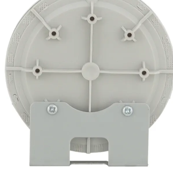
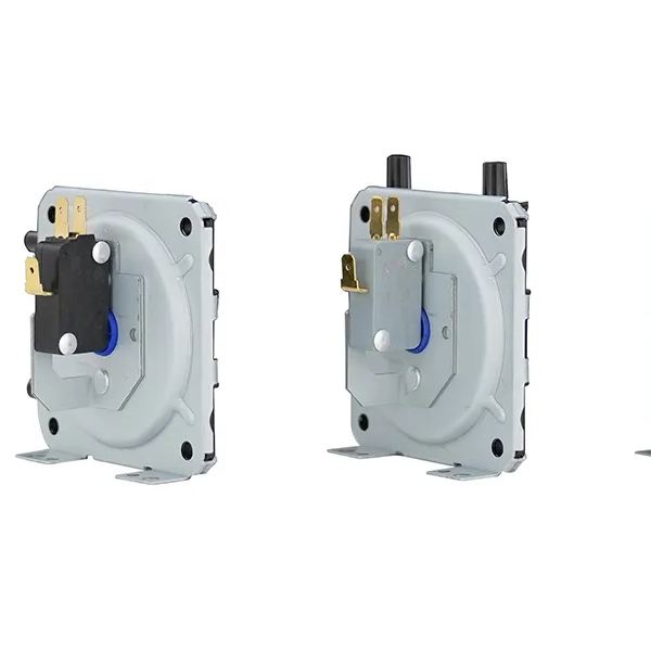
A pressure switch senses pressure changes in the system. When the pressure reaches a preset threshold, it triggers a mechanical or electronic signal to realize automatic control of equipment such as pumps and valves. Its core components include pressure-sensing elements (such as diaphragms, bellows), trigger mechanisms (such as springs, levers), and contact switches. Common types of pressure switches are mechanical (triggered by mechanical deformation) and electronic (converted into electrical signals through pressure sensors). The testing and adjustment logic of both is similar, but there are differences in operation details.
Before conducting tests and adjustments, three key parameters need to be clarified: set pressure (the pressure value at which the action is triggered), switching difference (the pressure difference between the triggering action and the reset action), and maximum working pressure (the maximum pressure allowed by the equipment). These parameters are usually marked on the nameplate of the pressure switch and can also be found in the equipment manual. For example, the set pressure of a pressure switch in a water supply system is 0.6MPa, and the switching difference is 0.1MPa. Then, when the system pressure rises to 0.6MPa, the switch will disconnect (stop water supply), and when it drops to 0.5MPa, the switch will close (start water supply).
II. Preparations Before Testing: System Safety Operations
Disconnect the power supply of the system where the pressure switch is located and close the relevant valves to ensure that the equipment will not start accidentally during the test;
Slowly release the residual pressure in the system by opening the exhaust valve or drain valve, and operate after the pressure gauge shows 0;
Check whether the connecting pipeline of the pressure switch has leakage, corrosion, or looseness. If there is a fault, it must be repaired before testing.
III. Testing Steps of the Pressure Switch
(I) Static Test (Offline Test)
1. Remove the pressure switch from the system, connect the pressure source, pressure gauge, and pressure switch with a pipeline, and ensure that the interface is well sealed;
2. Slowly increase the output pressure of the pressure source, and at the same time observe the reading of the pressure gauge and the on-off state of the multimeter (set the multimeter to the resistance range, and connect the test leads to the terminals of the pressure switch);
3. Record the pressure value when the contact of the pressure switch is disconnected (or closed), which is the measured set pressure;
4. Continue to increase the pressure to exceed the set pressure, then slowly reduce the pressure, record the pressure value when the contact is reset (closed or disconnected), and calculate the switching difference (the difference between the set pressure and the reset pressure);
5. Repeat the test 3 times. If the deviation of the three measured values is within the allowable range (usually ±2% of the set value), it indicates that the pressure switch performance is stable; if the deviation is too large, adjustment is required.
(II) Dynamic Test (Online Test)
1. Under the normal operation state of the system, observe whether the start-stop pressure of the equipment is consistent with the set value of the pressure switch;
2. Use a multimeter to monitor the contact state of the pressure switch in real-time, and record the reading of the pressure gauge at the same time to judge whether the switch action is accurate;
3. Simulate system pressure fluctuations (such as manually adjusting valves to change flow), and observe whether the pressure switch can respond in time at the set threshold to avoid frequent equipment actions or delayed protection.
IV. Adjustment Methods of the Pressure Switch
(I) Adjustment of Mechanical Pressure Switch
1. Mechanical pressure switches are usually equipped with two adjustment knobs, marked "SET" (set pressure) and "DIFF" (switching difference) respectively. Some products are adjusted through the same knob, which needs to be distinguished by referring to the instruction manual;
2. If the measured set pressure is lower than the standard value, rotate the "SET" knob clockwise (increase the spring preload); if it is higher than the standard value, rotate it counterclockwise;
3. When adjusting the switching difference, rotating the "DIFF" knob clockwise can increase the difference, and rotating it counterclockwise can decrease the difference;
4. After each adjustment, it is necessary to re-conduct the static test until the set pressure and switching difference meet the requirements. During the adjustment process, operate slowly to avoid component damage caused by excessive rotation.
(II) Adjustment of Electronic Pressure Switch
1. Electronic pressure switches set parameters through buttons or displays, and some need to be connected to special debugging software;
2. Enter the parameter setting mode, find the "upper pressure limit" and "lower pressure limit" options, and directly input the target values (the unit must be consistent with the system, such as MPa, bar);
3. Save the parameters after adjustment, restart the pressure switch, and confirm whether the set value is effective through the pressure source test;
4. Some electronic pressure switches support calibration functions. If the measurement accuracy deviates, zero calibration (calibration when the pressure is 0) and full-scale calibration (calibration by applying standard pressure) can be carried out according to the instruction manual.
V. Verification After Testing and Adjustment
1. After adjustment, reconnect the pressure switch to the system, check the tightness of the pipeline interface to avoid leakage;
2. Turn on the power, start the system, and observe whether the action of the equipment during the pressure rise and fall process meets expectations, such as whether the water pump starts and stops at the set pressure;
3. Run the system continuously for more than 30 minutes, monitor the stability of the pressure switch, and ensure that there is no misoperation or failure;
4. Record the test data (including the set value, measured value, ambient temperature before and after adjustment, etc.) and archive it as a reference for the next maintenance.


