
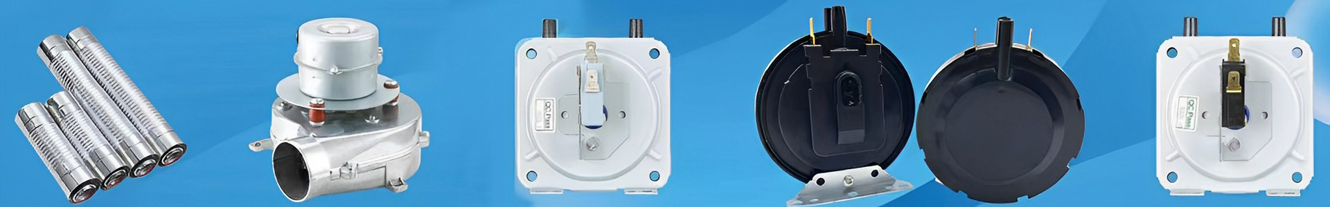


A pressure switch is a sensing element that realizes on-off control by utilizing changes in gas pressure, and it is widely used in scenarios such as air compressors, automotive air brakes, and industrial automation. Its core performance is determined by the range, set point, hysteresis, and repeatability, and the quality of installation directly affects the safety and service life of the system.
I. Pre-installation Preparation Work
Confirmation of Model Selection
Check the nameplate: working pressure range (e.g., 0.2–1.0 MPa), type of medium (dry air/non-corrosive gas), voltage level (DC24 V/AC220 V).
Electrical interface: plug type, terminal type, or direct cable outlet type, which needs to match the on-site wire harness.
Certification requirements: explosion-proof, UL, CE, etc., selected according to the usage environment.
Tools and Consumables
Tools: open-end wrench (specifications matching the interface), torque wrench, hex key, wire stripper, multimeter, soapy water or electronic leak detector.
Consumables: Teflon tape or thread sealant, grounding wire, label paper, cable ties.
Environmental and Location Inspection
Avoid direct sunlight, strong vibration, water dripping, and dust; the optimal ambient temperature is –10 °C ~ +60 °C.
The installation height should facilitate daily observation and maintenance; keep a distance of ≥0.5 m from heat sources.
Reserve sufficient space: ≥120 mm side clearance is required for wiring, adjusting knobs, and maintenance.

II. Core Installation Steps
Selection and Fixing of Installation Position
The installation position of the pressure switch must meet the three principles of "easy detection, avoiding interference, and safety and reliability":
Priority installation position: the side or top of the horizontal pipeline (to prevent liquid accumulation at the bottom of the pipeline from entering the switch sensing cavity), the straight-line distance from pipeline elbows and valves should not be less than 5 times the pipeline diameter (e.g., DN50 pipeline should be 250mm or more away from the valve) to reduce the impact of fluid disturbance on detection accuracy.
Fixing methods:
For light switches (weight < 0.5kg), they can be directly connected to the pipeline through threaded interfaces;
For heavy switches (weight ≥ 1kg) or in vibrating environments, additional metal brackets must be installed. The diameter of the fixing bolts between the bracket and the wall or equipment should not be less than M8, and the tightening torque is 25-30N・m.
When installing on vertical pipelines, the switch sensing element should face the horizontal direction to prevent condensed water from accumulating on the surface of the diaphragm or bellows.
Pipeline Interface Processing and Connection
Thread processing and cleaning: If the pipeline interface threads do not match, reprocess with a tap to ensure the thread accuracy reaches grade 6H. After processing, purge residual iron filings with compressed air. For rusty old pipeline interfaces, polish with sandpaper until the metal luster is exposed to remove the oxide layer.
Sealing treatment: Wrap Teflon tape around the threaded interface (clockwise, 10-15 layers, leaving 1-2 threads unwrapped at the end to prevent Teflon tape from entering the pipeline and blocking the switch), or evenly apply thread sealant (adhesive layer thickness 0.2-0.3mm). Note: Do not use sealant on the electrical interface of electronic signal pressure switches to prevent corrosion of the terminal blocks.
Connection and torque control: Hand-tighten the switch into the interface until it fits, then use a torque wrench to tighten to the specified torque (recommended torque for G1/4 interface is 15-20N・m, for NPT1/2 interface is 25-30N・m). Avoid over-tightening which may cause interface deformation or under-tightening which may cause leakage. During installation, keep the switch housing upright, with a vertical deviation from the pipeline axis not exceeding 5°.
Electrical Wiring Operation
Electrical wiring must be carried out in strict accordance with the switch nameplate and wiring diagram, with the following steps:
Power-off confirmation: Before wiring, turn off the power of the control system and use a multimeter to check the line voltage to ensure it is 0V.
Selection of wire specifications: Select the wire cross-sectional area according to the rated current of the switch (e.g., mechanical contact type is usually 5A/250VAC). The copper core wire should not be less than 0.75mm², and the wire must be protected by a pipe (metal pipe or PVC pipe, diameter ≥ 16mm).
Terminal block processing: Strip the wire insulation layer (length 5-7mm), twist the wire core into a bundle, insert it into the terminal, and tighten with a screwdriver (torque 0.5-0.8N・m) to ensure no looseness or virtual connection. For explosion-proof pressure switches, use a special explosion-proof gland to fix the wire. After tightening, check the sealing performance (spray with soapy water, no bubbles).
Shielding layer processing: If the switch is equipped with a shielding wire, the shielding layer must be grounded at one end (grounding resistance ≤ 4Ω) to avoid interference signals affecting electronic components.

Installation of Additional Components
Filter installation: When the medium contains impurities such as dust and oil mist, a filter must be installed 50-100mm upstream of the switch. The inlet and outlet directions of the filter must be consistent with the medium flow direction (marked "IN" on the housing is the inlet), and the regular sewage outlet should face the direction convenient for operation.
Parallel installation of pressure gauge: Install a pressure gauge in parallel next to the switch interface to observe the actual pressure value during subsequent debugging. The length of the connecting pipeline between the pressure gauge and the switch should not exceed 300mm to reduce pressure loss.
Installation of shock absorption devices: In environments with vibration frequency exceeding 30Hz (such as near air compressors), a shock absorber (rubber material, pressure resistance grade ≥ 1.5 times the maximum system pressure) must be installed between the switch and the pipeline, or a shock-absorbing pad should be placed between the bracket and the equipment to reduce the impact of vibration on the contact life.
The installation of pressure switches is a work that combines technology and standardization. Negligence in any link may affect the safety and efficiency of the system. From the early parameter checking to the later commissioning and acceptance, we must always follow the principles of "safety first, precision first, and scenario adaptation", and formulate targeted plans in combination with the special requirements of different industries. By strictly implementing the procedures and standards in this guide, the failure rate after installation can be effectively reduced (statistics show that standardized installation can reduce the early failure of pressure switches by more than 70%), laying a solid foundation for the stable operation of the pneumatic system. In actual operation, it is also necessary to combine the specific requirements of the product manual and consult the manufacturer's technical personnel when necessary to ensure that the installation quality meets the design standards.